Serial Communication (USART) for PIC Microcontroller
PIC Microcontroller
Serial Communication (USART) for PIC Micro-controller
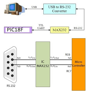
PIC microcontroller has Universal synchronous Asynchronous receiver transmitter block. RS 232 protocol can be used to transmit and receive data using USART block.

RC6 port terminal is used as the transmitter pin (TXD).
RC7 pin is used as receiver pin (RXD)
The registers associated with USART block are explained below.
TXSTA – Transmit Status and Control Register

- Bit 7 CSRC : Clock Source Select Bit, this bit has no application in the Asynchronous mode. ( 0)
- Bit 6 TX9 : When this bit is set it enables the 9-bit transmission otherwise 8-bit transmission is used. 9th bit in the 9-bit transmission mode is commonly used as a parity bit. (0)
- Bit 5 TXEN : Setting this bit enables the transmission. (1)
- Bit 4 SYNC : This is the USART Mode select bit. Setting this bit selects Synchronous mode while clearing this bit selects the Asynchronous mode. (0)
- Bit 3 Unimplemented : This bit is unimplemented and will read as 0.
- Bit 2 BRGH : This is the High Baud Rate Select bit for Asynchronous mode operation and is unused in Synchronous mode. Setting this bit selects High Speed and clearing this bit selects Low-Speed baud rates. (0)
- Bit 1 TRMT : This is the Transmit Shift Register (TSR) status bit. This can be used to check whether the data written to transmit register is transmitted or not. When the TRS is empty this bit is set and when the TSR is full this bit will be 0. (0)
- Bit 0 TX9D : This is the 9th bit of data in the 9-bit transmission mode. This is commonly used as a parity bit. (0)
( Initialize TXSTA =0b00100000)
RCSTA – Receive Status and Control Register

- Bit 7 SPEN : Serial Port Enable bit. Setting this bit enables serial port and configures RC7, RC6 as serial port pins. (1)
- Bit 6 RX9 : Setting this bit enables 9 bit reception otherwise it will be in 8 bit reception mode. (0)
- Bit 5 SREN : Single Receive Enable bit. This bit has no effect on Asynchronous mode and Synchronous Slave mode. Setting this bit will enables Single Receive. This bit will cleared after the reception is complete. (0)
- Bit 4 CREN : Continuous Receive Enable bit. Setting this bit will enable Continuous Receive. In the Synchronous Mode CREN overrides SREN. (1)
- Bit 3 ADDEN : Address Detect Enable bit. This bit is applicable only in Asynchronous 9 bit mode. Setting this bit enables Address Detect. (0)
- Bit 2 FERR : Framing Error bit. 1 at this bit stands for Framing Error while 0 stands for No Framing Error. (0)
- Bit 1 OERR : Overrun Error bit. A high at this bit indicates that Overrun error has occured. ())
- Bit 0 RX9D : This is the 9th bit of Received Data and is commonly used as Parity Bit. (0)
(Initialize RCSTA = 0b10010000 )
USART Baud Rate Generator (BRG)
Baud Rate Generator provides the required clock for the data transmission and reception. USART module has a dedicated 8-bit baud rate generator which supports both Synchronous and Asynchronous modes. The 8-bit SPBRG register controls the time period of this free running timer. In Asynchronous mode BRGH, 2nd bit of TXSTA register also controls the generated baud rate but in the Synchronous mode, it is ignored. Baud Rate can be calculated from the following equations, where FOSC is the clock frequency of the microcontroller.
BRGH = 0: low baud rate.
n = Fosc / [64 * (SPBRG + 1)]
i.e. SPBRG = [Fosc / (64 * n)] – 1
for Fosc = 48MHz, n = 9600, we get SPBRG = 4E H
/* Program to transmit string serially from PIC to PC */
#include<p18F4550.h>
void delay()
{
unsigned int i;
for(i=0;i<=30000;i++);
}
void main(void)
{
unsigned char data,i;
unsigned char s[]={'H','E','L','L','O','-','W','O','R','L','D','.'};
TRISCbits.RC6 = 0; //Configure TX pin set as output (RC6)
SPBRG = 0X4E; // Set Baud Rate (X value)
TXSTA = 0b00100000; //Asynchronous 8-bit; Transmit enabled; Low speed //baud rate select
RCSTA = 0b10010000; // Enable Serial Port and continuous receive enable pin
for(i=0;i<12;i++)
{
data=s[i];
TXREG =data ; // Data to be transmitted is loaded in TXREG register
while(PIR1bits.TXIF == 0); //Wait while transmit register is empty
delay();
}
while(1);
}
Watch the video to understand program :
Watch the video to understand program :